Requirements & Process
Review your material, dimensions, process and throughput to define equipment requirements.
A four-column hydraulic press for drawing, stamping, bending and other pressing operations, with reference jog, semi-automatic and automatic modes.
Reference specifications require confirmation. Source ↗
01 / EQUIPMENT OVERVIEW
Structure and manufacture
The main body and control units are connected by piping and electrical equipment. Reference assemblies include the frame, main cylinder, knockout cylinder, hydraulic drive, limit switches and control cabinet. The source describes machining-center processing, forged 45-grade-steel columns with hardening and chrome plating, and a forged main rod with SKF seals.
Hydraulics and controls
The hydraulic system and tank are located on top of the machine. High-pressure pumps, a low-pressure control circuit and valves provide sequential operation. Reference modes include PLC-controlled jog, semi-automatic and automatic operation, with hydraulic/electrical overload protection and water cooling. Working pressure, pressing speed, rapid descent and reduced-speed pressing can be set for the process.
Applications
Listed uses include pressing plastic materials, forming powder and plastic products, hot/cold metal extrusion, sheet drawing, stamping, bending, flanging, straightening and press-fitting. Material, tooling, load and stroke compatibility require confirmation.
Reference components
The source illustrates floor-type CNC boring/milling, Taifeng valves, a high-pressure pump, forged 45-grade-steel cylinders and columns, and a PLC cabinet. Confirm the actual brands and operating modes in the technical agreement. Source electrical-compliance descriptions are not certification for equipment offered here.
02 / SPECIFICATIONS
Reference specifications from the source. Labels, unit notation and table structure have been standardized without changing numeric data. Items marked Verify require a confirmed technical datasheet.
Swipe or scroll horizontally to compare models →
| Parameter | Unit | Y27-63 | Y27-100 | Y27-200 | Y27-315 |
|---|---|---|---|---|---|
| Nominal Force | kN | 630 | 1000 | 2000 | 3150 |
| Max Liquid Working Force | MPa | 25 | 25 | 25 | 25 |
| Hydraulic Cushion Force | kN | 200 | 300 | 600 | 1250 |
| Max Stroke of Hydraulic Cushion | mm | 180 | 300 | 250 | 300 |
| Size of the Hydraulic Cushion | mm | 310x300 | 470x430 | 800x630 | 900x800 |
| Max Opening Height | mm | 900 | 1000 | 1120 | 1250 |
| Slide Stroke | mm | 450 | 700 | 710 | 800 |
| Slide Speed (Descent) | mm/s | 120 | 150 | 100 | 100 |
| Slide Speed (Working) | mm/s | 11-15 | 20 | 6-15 | 6-12 |
| Slide Speed (Return) | mm/s | 130 | 80 | 80 | 60 |
| Working Table Size | mm | 560x500 | 720x580 | 1000x900 | 1250x1120 |
| Motor Power | kW | 11 | 11 | 22 | 22 |
| Parameter | Unit | Y27-500 | Y27-630 | Y27-1000 |
|---|---|---|---|---|
| Nominal Force | kN | 5000 | 6300 | 10000 |
| Max Liquid Working Force | MPa | 25 | 25 | 25 |
| Hydraulic Cushion Force | kN | 1600 | 2500 | 3000 |
| Max Stroke of Hydraulic Cushion | mm | 350 | 400 | 350 |
| Size of the Hydraulic Cushion | mm | 1100x1100 | 1950x1200 | 2000x1500 |
| Max Opening Height | mm | 1500 | 1600 | 2300 |
| Slide Stroke | mm | 900 | 1000 | 1400 |
| Slide Speed (Descent) | mm/s | 140 | 100 | 100 |
| Slide Speed (Working) | mm/s | 5-15 | 6-14 | 13 |
| Slide Speed (Return) | mm/s | 70 | 65 | 60 |
| Working Table Size | mm | 1400x1400 | 2600x1750 | 2500x2000 |
| Motor Power | kW | 45 | 45 | 90 |
04 / IN MOTION
Review your material, dimensions, process and throughput to define equipment requirements.
Compare models and specifications and discuss tooling, feeding and automation options.
Confirm configuration, delivery, installation and support scope for the project. Arrangements are subject to agreement.
Share material, thickness, workpiece dimensions, process and throughput. Models and specifications support initial comparison; suitability depends on the application.
Some source data contains model, unit or value inconsistencies. Original values are retained with notes. Request confirmed technical documentation before selection or ordering.
Describe tooling, feeding, loading and production-line integration requirements in your inquiry. Feasibility and scope are assessed for the project.
Download available documents or use the inquiry form to specify required documentation, destination and schedule. Final configuration, timing and service scope are subject to confirmation.
LET’S TALK EQUIPMENT
Share material, dimensions and required throughput so our team can review the application.
Y27 Hydraulic Press
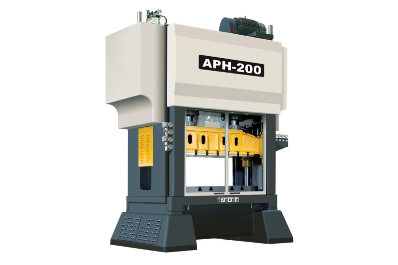
APH-125 · APH-200 +1
A high-speed press for continuous stamping, with reference features including variable-speed control, automatic lubrication and overload protection.
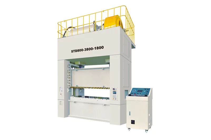
STD-300 · STD-400 +5
A straight-side, double-crank press with multiple reference models and stroke configurations for stamping projects requiring a large working area.
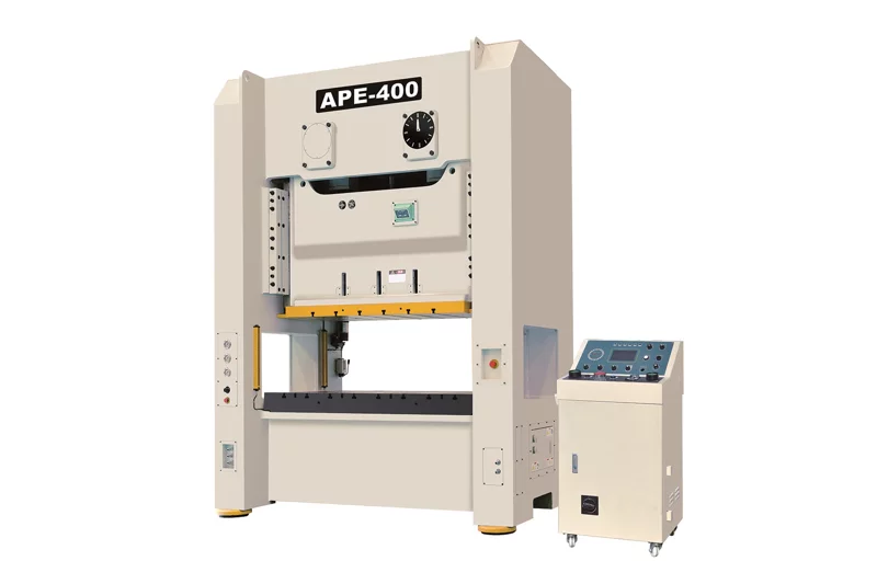
APE-160 · APE-200 +5
An H-frame two-point press series with reference ram-adjustment, lubrication and overload-protection features. Confirm tooling and loading requirements before selection.
LET’S BUILD SOMETHING BETTER