Requirements & Process
Review your material, dimensions, process and throughput to define equipment requirements.
A reference multi-axis servo/hydraulic tube bender with feeding, rotation and multi-stack tooling options selected for the tube and bending process.
Reference specifications require confirmation. Source ↗
01 / EQUIPMENT OVERVIEW
CNC and automation
The source describes multi-axis servos and multi-stack tooling and refers to a GBEMA design background, which has not been independently verified. Listed functions include feeding, rotation, tool changes, drawing input, process-document editing and data correction. Reference extensions include robotic handling, inspection-based process correction, diagnostics, 3D visualization/simulation and interference checks. One to nine tooling stacks are optional and must be confirmed by model.
Frame and hydraulics
The welded frame is heat-treated and floor-type CNC bored/milled. YUKEN hydraulics and pumps are referenced. Bend, clamp and pressure dies, plus optional mandrel/wiper tooling, are described as 42CrMo with wire-EDM and CNC machining.
Controls and operation
The source lists Mitsubishi PLCs, Schneider electrical components and a Chinese/English touchscreen for bending angle, feed length and rotation. Modes include manual, semi-automatic and automatic.
Drive options
Standard bending is described as hydraulic-cylinder driven; Mitsubishi servo bending is optional. Select the drive for the required cycle, material and accuracy.
Selection data
Provide outside diameter, wall thickness, material, radius, bend angle and a 3D part drawing. The source repeats two maximum-OD/wall-thickness rows without stating their materials or conditions. They remain separate and flagged rather than being merged.
02 / SPECIFICATIONS
Reference specifications from the source. Labels, unit notation and table structure have been standardized without changing numeric data. Items marked Verify require a confirmed technical datasheet.
Swipe or scroll horizontally to compare models →
| Parameter | Unit | A15CNC | A25CNC | A38CNC | A50CNC |
|---|---|---|---|---|---|
| Max. OD× WT | mm | 19.05×1.5 | 25.4×1.5 | 38.1×2 | 50.8×2.5 |
| Max. OD× WT [source row 2]Verify | mm | 15.88×1.5 | 19.05×1.5 | 31.75×1.5 | 44.45×2 |
| Max. Square Tube × WT | mm | 15×1.5 | 20×1.5 | 30×1.5 | 40×2 |
| Max. Round Bar | mm | 12 | 18 | 25 | 32 |
| Max. Bending Radius | mm | 100 | 100 | 160 | 200 |
| Mandrel Working Distance | mm | 1200 | 1500 | 1900 | 2300 |
| Max. Bending Angle | deg | 0-190 | 0-190 | 0-190 | 0-190 |
| Tube Bending Speed | deg | 200 | 180 | 180 | 110 |
| Feeding Speed | — | 1300 | 1300 | 1200 | 1200 |
| Rotating Speed | — | 360 | 360 | 360 | 270 |
| Feeding/Rotating/Bending Precision | mm | ±0.1 | ±0.1 | ±0.1 | ±0.1 |
| Max. Working Pressure | MPa | 14 | 14 | 17.5 | 17.5 |
| Pump Motor | kW | 2.2 | 4 | 5.5 | 7.5 |
| Oil Tank Capacity | L | 160 | 210 | 250 | 300 |
| Overall Weight | Kg | 850 | 1000 | 1500 | 200 |
| Operating Height | mm | 900 | 1015 | 1015 | 1100 |
| LxWxH | mm | 2400x700x1300 | 3500x800x1350 | 4000x850x1400 | 4900x1050x1400 |
| Parameter | Unit | A63CNC | A75CNC | A89CNC |
|---|---|---|---|---|
| Max. OD× WT | mm | 63.5X3 | 76.2×3 | 88.9×4 |
| Max. OD× WT [source row 2]Verify | mm | 63.5X1.5 | 76.2×1.5 | 88.9×2 |
| Max. Square Tube × WT | mm | 50X2.5 | 60×3 | 70×3.5 |
| Max. Round Bar | mm | 38 | 45 | 55 |
| Max. Bending Radius | mm | 270 | 280 | 350 |
| Mandrel Working Distance | mm | 2800 | 3000 | 3300 |
| Max. Bending Angle | deg | 0-190 | 0-190 | 0-190 |
| Tube Bending Speed | deg | 100 | 90 | 80 |
| Feeding Speed | — | 900 | 800 | 800 |
| Rotating Speed | — | 250 | 250 | 240 |
| Feeding/Rotating/Bending Precision | mm | ±0.1 | ±0.1 | ±0.1 |
| Max. Working Pressure | MPa | 17.5 | 17.5 | 17.5 |
| Pump Motor | kW | 7.5 | 11 | 15 |
| Oil Tank Capacity | L | 300 | 380 | 500 |
| Overall Weight | Kg | 2900 | 3500 | 4500 |
| Operating Height | mm | 1100 | 1150 | 1200 |
| LxWxH | mm | 4900x1050x1500 | 5300x1300x1550 | 6000x1600x1550 |
04 / IN MOTION
Review your material, dimensions, process and throughput to define equipment requirements.
Compare models and specifications and discuss tooling, feeding and automation options.
Confirm configuration, delivery, installation and support scope for the project. Arrangements are subject to agreement.
Share material, thickness, workpiece dimensions, process and throughput. Models and specifications support initial comparison; suitability depends on the application.
Some source data contains model, unit or value inconsistencies. Original values are retained with notes. Request confirmed technical documentation before selection or ordering.
Describe tooling, feeding, loading and production-line integration requirements in your inquiry. Feasibility and scope are assessed for the project.
Download available documents or use the inquiry form to specify required documentation, destination and schedule. Final configuration, timing and service scope are subject to confirmation.
LET’S TALK EQUIPMENT
Share material, dimensions and required throughput so our team can review the application.
CNC Tube Bending Machine
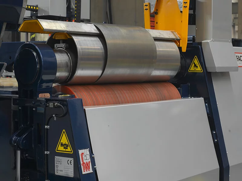
Two Roller Rolling Machine
A reference two-roll system combining a steel roll and an elastomer-covered roll, using clamping pressure and rotation to form sheet metal under PLC control.
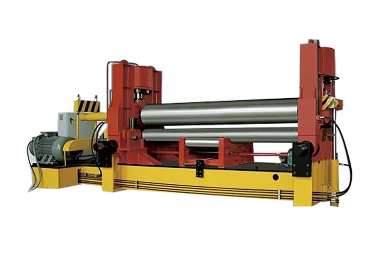
W11S-12X2000 · W11S-16X2000 +22
A three-roll system with vertical and horizontal upper-roll movement for pre-bending and rolling, with adjustable support rolls and digital position indication.
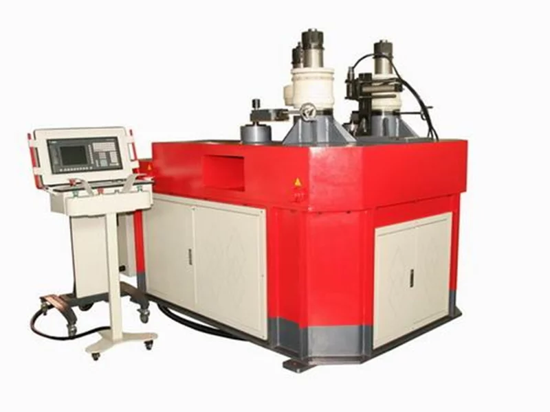
RR 100-TNC
A reference profile-bending system with three hydraulically driven rolls and servo-controlled curvature adjustment for angle, flat bar, round tube and other sections.
LET’S BUILD SOMETHING BETTER