Requirements & Process
Review your material, dimensions, process and throughput to define equipment requirements.
A reference hydraulic four-roll system with upper/lower-roll clamping for pre-bending and rolling, with project-dependent feeding and discharge automation.
Reference specifications require confirmation. Source ↗
01 / EQUIPMENT OVERVIEW
Structure and process
The source describes a torsion-synchronized, hydraulically driven four-roll arrangement with upper/lower-roll clamping, bilateral pre-bending, alignment and rolling. Hydraulic and overload protection are reference features. Maintenance-free and minimum-diameter claims lack operating conditions and are not substituted for maintenance instructions or forming trials. The source’s “1.4–0.5 times” diameter comparison is ambiguous and is not treated as a usable capacity.
Components
Reference components include ZWZ double-row self-aligning bearings; 42CrMo forged working rolls, listed at HRC50–55 and sourced from Nanjing Iron and Steel Group; and a stress-relieved, CNC-machined Q235B frame and base. Planetary reducers and radial-piston hydraulic motors are identified as EF/ZC. Main electrical components are listed as SIEMENS. Hydraulic references include an HCHC gear pump, NORTHMAN valves, 45-grade-steel main cylinders listed at HRC48–50 from Jiangsu Opu/Jiujiu, and Yx-type seals from Taiwan Dingji. Touchscreen and PLC references are SIEMENS, with OMRON encoders and sensors. Confirm all brands, materials and hardness values against the delivery specification.
Frame and rolls
The welded frame and base are inspected, annealed and CNC-machined. Forged 42CrMo upper and lower rolls use self-aligning bearings to accommodate shaft inclination and uneven loads during cone rolling. The source describes two self-aligning bearings per roll shaft. Lubrication intervals remain subject to the manufacturer’s maintenance instructions.
Clamping and motion
Upper/lower-roll drive supports clamping and feeding, keeping the plate edge close to the pinch point during pre-bending. Proportional valves control leveling of the lower and side rolls. The listed ±0.1 mm leveling accuracy requires confirmation of test conditions.
Feeding platform
Vacuum cups place the sheet on the platform, a pneumatic unit centers it, and a servo drive advances it. Listed figures include a 2.5 m platform width, 700–2500 mm sheet width, 1500–4000 mm sheet length, 4.2 m platform length, 750 mm height, one centering set with two groups, 35-grade-steel feed rolls, 5000 kg loading, approximately 5 m/min feed speed and 1.5 kW feed power. The feed-roll diameter is written as “φ120m”; the unit is questionable and has not been silently changed to millimeters.
Cone rolling and discharge
A guide-wheel arrangement mounted on the lower roll supports cone positioning. The discharge mechanism lifts the rolled shell before pushing it along the roll axis, reducing contact with the work rolls. Support for curved parts must be confirmed for the intended tooling.
Transfer and control
The transfer trolley uses a motor, reducer, transmission, rollers and supports to receive the workpiece and move it onward. Rubber rollers are described for surface protection and shock absorption. HMI programming and line-level CNC control are listed. Side supports, overhead supports, feed rolls and lower-roll drive can be optional; confirm the final arrangement against layout drawings and the component schedule.
02 / SPECIFICATIONS
Reference specifications from the source. Labels, unit notation and table structure have been standardized without changing numeric data. Items marked Verify require a confirmed technical datasheet.
Swipe or scroll horizontally to compare models →
| Parameter | Unit | W12-6X2000 | W12-6X2500 | W12-8X2000 | W12-8X2500 |
|---|---|---|---|---|---|
| Max. Thickness | mm | 6 | 6 | 8 | 8 |
| Max. Length | mm | 2000 | 2500 | 2000 | 2500 |
| Strength | MPa | 245 | 245 | 245 | 245 |
| Rolling Speed | m/min | 4 | 4 | 4 | 4 |
| Min. Dia. at Full-load | mm | 500 | 600 | 700 | 750 |
| Upper Roller Diameter | mm | 250 | 250 | 280 | 300 |
| Lower Roller Diameter | mm | 190 | 190 | 260 | 280 |
| Side Roller Diameter | mm | 180 | 185 | 180 | 230 |
| Power | kW | 5.5 | 7.5 | 11 | 15 |
| Parameter | Unit | W12-12*2000 | W12-12*2500 | W12-12*3200 | W12-20*2000 |
|---|---|---|---|---|---|
| Max. Thickness | mm | 12 | 12 | 12 | 20 |
| Max. Length | mm | 2000 | 2500 | 3200 | 2000 |
| Strength | MPa | 245 | 245 | 245 | 245 |
| Rolling Speed | m/min | 4 | 4 | 4 | 4 |
| Min. Dia. at Full-load | mm | 750 | 750 | 800 | 800 |
| Upper Roller Diameter | mm | 300 | 340 | 350 | 350 |
| Lower Roller Diameter | mm | 280 | 300 | 320 | 320 |
| Side Roller Diameter | mm | 230 | 260 | 240 | 240 |
| Power | kW | 18 | 22 | 18 | 18 |
| Parameter | Unit | W12-25*2000 | W12-20*2500 | W12-30*2000 | W12-25*2500 |
|---|---|---|---|---|---|
| Max. Thickness | mm | 25 | 20 | 30 | 25 |
| Max. Length | mm | 2000 | 2500 | 2000 | 2500 |
| Strength | MPa | 245 | 245 | 245 | 245 |
| Rolling Speed | m/min | 4 | 4 | 4 | 4 |
| Min. Dia. at Full-load | mm | 800 | 640 | 1000 | 800 |
| Upper Roller Diameter | mm | 350 | 350 | 400 | 400 |
| Lower Roller Diameter | mm | 320 | 320 | 360 | 360 |
| Side Roller Diameter | mm | 240 | 240 | 240 | 240 |
| Power | kW | 22 | 30 | 37 | 37 |
| Parameter | Unit | W12-35*2000 | W12-30*2500 | W12-40*2000 | W12-45*2000 |
|---|---|---|---|---|---|
| Max. Thickness | mm | 35 | 30 | 40 | 45 |
| Max. Length | mm | 2000 | 2500 | 2000 | 2000 |
| Strength | MPa | 245 | 245 | 245 | 245 |
| Rolling Speed | m/min | 4 | 4 | 4 | 4 |
| Min. Dia. at Full-load | mm | 1200 | 1000 | 1400 | 1600 |
| Upper Roller Diameter | mm | 420 | 400 | 480 | 500 |
| Lower Roller Diameter | mm | 380 | 360 | 400 | 450 |
| Side Roller Diameter | mm | 210 | 230 | 420 | 280 |
| Power | kW | 37 | 37 | 45 | 45 |
| Parameter | Unit | W12-35*2500 | W12-40*2500 |
|---|---|---|---|
| Max. Thickness | mm | 35 | 40 |
| Max. Length | mm | 2500 | 2500 |
| Strength | MPa | 245 | 245 |
| Rolling Speed | m/min | 4 | 4 |
| Min. Dia. at Full-load | mm | 1200 | 1400 |
| Upper Roller Diameter | mm | 480 | 500 |
| Lower Roller Diameter | mm | 400 | 450 |
| Side Roller Diameter | mm | 420 | 380 |
| Power | kW | 45 | 45 |
From the source platform description; not a standard configuration for every W12 model. Diameter is written as φ120m and has not been changed to mm.
| Parameter | Unit | Feeding platform |
|---|---|---|
| Platform width | m | 2.5 |
| Sheet width | mm | 700–2500 |
| Sheet length | mm | 1500–4000 |
| Platform length | m | 4.2 |
| Platform height | mm | 750 |
| Centering device | set | 1 (2 groups) |
| Feed-roll material | — | 35# steel |
| Platform loading | kg | 5000 |
| Feed-roll diameter (source unit unclear)Verify | source: m | φ120 |
| Approximate feed speed | m/min | 5 |
| Feed power | kW | 1.5 |
04 / IN MOTION
Review your material, dimensions, process and throughput to define equipment requirements.
Compare models and specifications and discuss tooling, feeding and automation options.
Confirm configuration, delivery, installation and support scope for the project. Arrangements are subject to agreement.
Share material, thickness, workpiece dimensions, process and throughput. Models and specifications support initial comparison; suitability depends on the application.
Some source data contains model, unit or value inconsistencies. Original values are retained with notes. Request confirmed technical documentation before selection or ordering.
Describe tooling, feeding, loading and production-line integration requirements in your inquiry. Feasibility and scope are assessed for the project.
Download available documents or use the inquiry form to specify required documentation, destination and schedule. Final configuration, timing and service scope are subject to confirmation.
LET’S TALK EQUIPMENT
Share material, dimensions and required throughput so our team can review the application.
Four-Roll Plate Rolling Machine
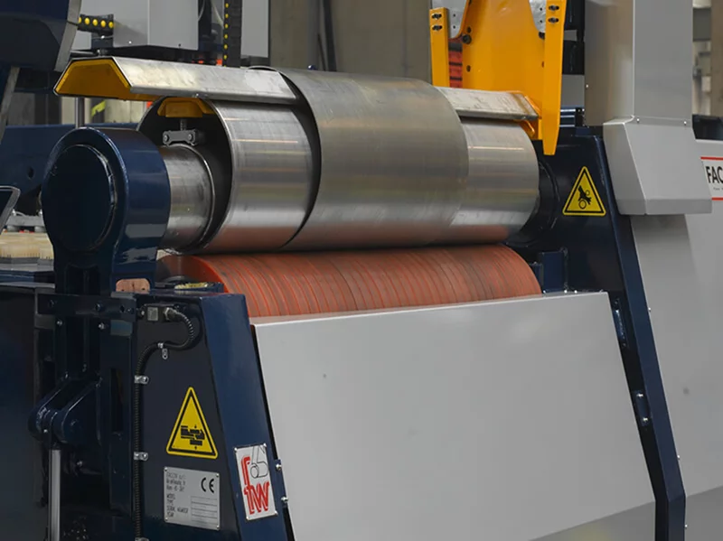
Two Roller Rolling Machine
A reference two-roll system combining a steel roll and an elastomer-covered roll, using clamping pressure and rotation to form sheet metal under PLC control.
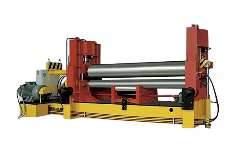
W11S-12X2000 · W11S-16X2000 +22
A three-roll system with vertical and horizontal upper-roll movement for pre-bending and rolling, with adjustable support rolls and digital position indication.
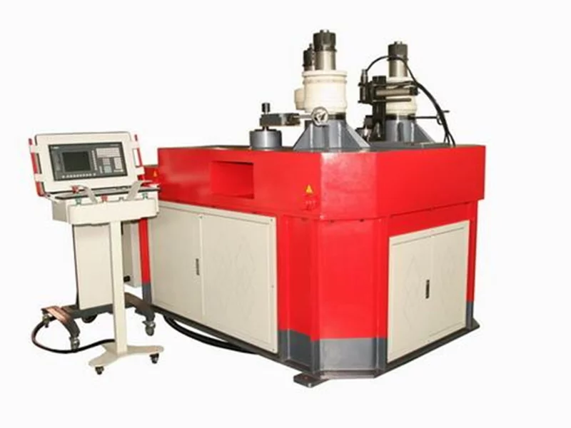
RR 100-TNC
A reference profile-bending system with three hydraulically driven rolls and servo-controlled curvature adjustment for angle, flat bar, round tube and other sections.
LET’S BUILD SOMETHING BETTER