Requirements & Process
Review your material, dimensions, process and throughput to define equipment requirements.
A reference hydraulic press brake with electro-hydraulic cylinder synchronization and mechanical crowning, with backgauge and handling options to be confirmed per application.
Reference specifications require confirmation. Source ↗
01 / EQUIPMENT OVERVIEW
Electro-hydraulic synchronization
The reference system controls the two cylinders and ram position for bending. Synchronization, bending and repeatability figures require defined technical limits and a bending trial.
Mechanical crowning
CNC-adjusted mechanical compensation addresses ram/worktable deflection. Two-way adjustment and multiple compensation points are described for cross-machine and longitudinal correction and bend consistency.
Compensation drive and worktable
The source describes single-plate-thickness compensation, a dedicated reducer, a precision potentiometer and a single-plate worktable. Comparisons with hydraulic compensation lack stated validation conditions; confirm performance and service-life requirements through documentation and acceptance tests.
Frame and hydraulics
The welded frame is five-face CNC-machined. Integrated hydraulics reduce external piping and support maintenance. Automatic loading/unloading can be reviewed for a specific project.
Selection review
Some source model names do not align with the listed maximum force or bending length. Original values remain flagged. Confirm force, effective length, column distance, throat, stroke, opening height and operating speeds before purchase.
02 / SPECIFICATIONS
Reference specifications from the source. Labels, unit notation and table structure have been standardized without changing numeric data. Items marked Verify require a confirmed technical datasheet.
Some source model-to-capacity or thickness mappings appear inconsistent. Values remain in their original columns and must be checked against an approved datasheet.
Swipe or scroll horizontally to compare models →
| Parameter | Unit | 30/1050 | 50/1300 | 60/1500 | 60/2050 |
|---|---|---|---|---|---|
| Max. Bending ForceVerify | kN | 2250 | 1500 | 1500 | 1000 |
| Max. Bending Length | mm | 3100 | 4100 | 3100 | 4100 |
| Column Distance | mm | 2600 | 3600 | 2600 | 3600 |
| Throat Depth | mm | 400 | 400 | 400 | 400 |
| Ram Stroke | mm | 215 | 215 | 215 | 215 |
| Closed Height | mm | 480 | 420 | 420 | 420 |
| Approaching Speed | mm/s | 110 | 130 | 120 | 160 |
| Working Speed | mm/s | 8 | 9 | 9 | 10 |
| Return Speed | mm/s | 90 | 110 | 110 | 120 |
| Main Motor Power | kW | 15 | 11 | 11 | 7.5 |
Some source model-to-capacity or thickness mappings appear inconsistent. Values remain in their original columns and must be checked against an approved datasheet.
| Parameter | Unit | 60/2550 | 100/3100 | 100/4100 | 150/3100 |
|---|---|---|---|---|---|
| Max. Bending ForceVerify | kN | 1000 | 600 | 600 | 600 |
| Max. Bending Length | mm | 3100 | 2550 | 2050 | 1500 |
| Column Distance | mm | 2600 | 2000 | 1600 | 1100 |
| Throat Depth | mm | 400 | 300 | 300 | 300 |
| Ram Stroke | mm | 215 | 165 | 165 | 165 |
| Closed Height | mm | 420 | 420 | 420 | 420 |
| Approaching Speed | mm/s | 160 | 150 | 150 | 150 |
| Working Speed | mm/s | 10 | 11 | 11 | 11 |
| Return Speed | mm/s | 130 | 120 | 120 | 120 |
| Main Motor Power | kW | 7.5 | 5.5 | 5.5 | 5.5 |
Some source model-to-capacity or thickness mappings appear inconsistent. Values remain in their original columns and must be checked against an approved datasheet.
| Parameter | Unit | 150/4100 | 225/3100 | 225/4100 | 320/3100 |
|---|---|---|---|---|---|
| Max. Bending ForceVerify | kN | 500 | 300 | 2250 | 3200 |
| Max. Bending Length | mm | 1300 | 1050 | 4100 | 3100 |
| Column Distance | mm | 900 | 700 | 3600 | 2600 |
| Throat Depth | mm | 300 | 300 | 400 | 400 |
| Ram Stroke | mm | 165 | 165 | 215 | 265 |
| Closed Height | mm | 420 | 420 | 480 | 530 |
| Approaching Speed | mm/s | 160 | 160 | 120 | 80 |
| Working Speed | mm/s | 10 | 10 | 8 | 8 |
| Return Speed | mm/s | 120 | 120 | 90 | 85 |
| Main Motor Power | kW | 5.5 | 4 | 15 | 22 |
Some source model-to-capacity or thickness mappings appear inconsistent. Values remain in their original columns and must be checked against an approved datasheet.
| Parameter | Unit | 320/4100 | 400/3100 | 400/4100 |
|---|---|---|---|---|
| Max. Bending ForceVerify | kN | 3200 | 4000 | 4000 |
| Max. Bending Length | mm | 4100 | 3100 | 4100 |
| Column Distance | mm | 3600 | 2600 | 3600 |
| Throat Depth | mm | 400 | 400 | 400 |
| Ram Stroke | mm | 265 | 265 | 265 |
| Closed Height | mm | 530 | 530 | 530 |
| Approaching Speed | mm/s | 90 | 100 | 110 |
| Working Speed | mm/s | 8 | 8 | 8 |
| Return Speed | mm/s | 85 | 85 | 85 |
| Main Motor Power | kW | 22 | 30 | 30 |
04 / IN MOTION
Review your material, dimensions, process and throughput to define equipment requirements.
Compare models and specifications and discuss tooling, feeding and automation options.
Confirm configuration, delivery, installation and support scope for the project. Arrangements are subject to agreement.
Share material, thickness, workpiece dimensions, process and throughput. Models and specifications support initial comparison; suitability depends on the application.
Some source data contains model, unit or value inconsistencies. Original values are retained with notes. Request confirmed technical documentation before selection or ordering.
Describe tooling, feeding, loading and production-line integration requirements in your inquiry. Feasibility and scope are assessed for the project.
Download available documents or use the inquiry form to specify required documentation, destination and schedule. Final configuration, timing and service scope are subject to confirmation.
LET’S TALK EQUIPMENT
Share material, dimensions and required throughput so our team can review the application.
CNC Hydraulic Press Brake
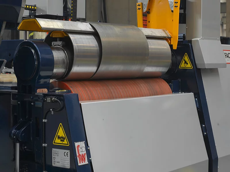
Two Roller Rolling Machine
A reference two-roll system combining a steel roll and an elastomer-covered roll, using clamping pressure and rotation to form sheet metal under PLC control.
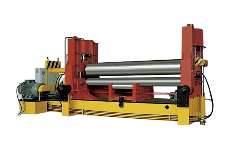
W11S-12X2000 · W11S-16X2000 +22
A three-roll system with vertical and horizontal upper-roll movement for pre-bending and rolling, with adjustable support rolls and digital position indication.
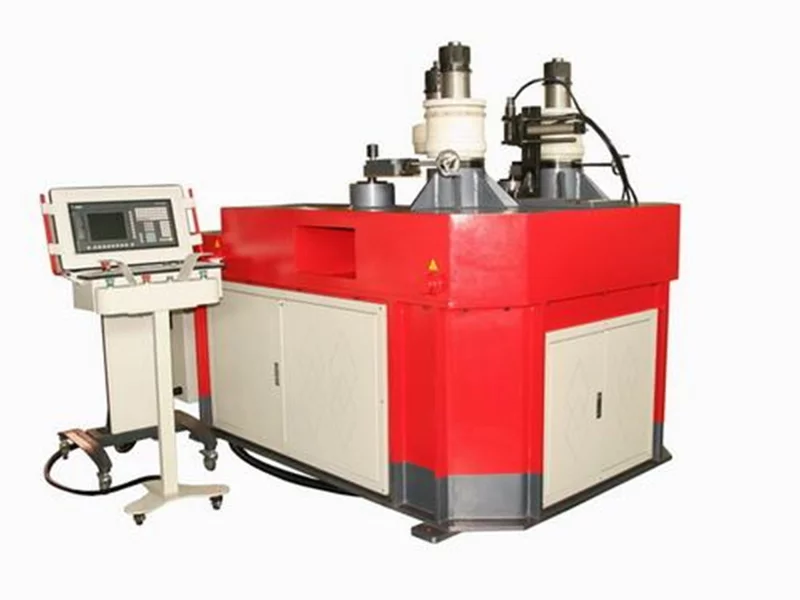
RR 100-TNC
A reference profile-bending system with three hydraulically driven rolls and servo-controlled curvature adjustment for angle, flat bar, round tube and other sections.
LET’S BUILD SOMETHING BETTER