Requirements & Process
Review your material, dimensions, process and throughput to define equipment requirements.
A reference all-electric servo panel bender with automatic sheet positioning and rotation, positive/negative bending and 2D DXF programming features.
Reference specifications require confirmation. Source ↗
01 / EQUIPMENT OVERVIEW
Equipment and structure
The source uses KISTON, Wisdom and EMBC names and refers to other suppliers’ design concepts; these identities and design-origin claims have not been independently verified. Reference features include an integral frame, direct-drive sheet rotation and a C-type bending unit. The frame is described as Q345 steel, CO₂-shielded welded and heat-treated to relieve welding stress, with finite-element analysis used during design.
Servo drive and sheet handling
Servo motors control the axes. The sheet is automatically positioned and rotated for multi-side positive and negative bending after initial positioning. Upper/lower pressure plates hold the sheet, and a DD motor provides rotation. Automatic lubrication, lower noise and reduced energy consumption are source descriptions requiring defined acceptance conditions.
Bending unit and tools
A C-type unit and controlled bending paths are intended to limit surface marking. The upper hold-down assembly adjusts effective tool length to the sheet, reducing manual tooling changes. Box-clearance and movable-unit arrangements address more complex parts. Customized equipment and achievable geometries require application review and bending trials.
Programming and processes
The source describes EtherCAT control, 2D programming and DXF import. Listed processes include positive/negative bending, arc bending, flattening and special bends. Automation still requires guarding and a safety assessment; it does not eliminate injury risks.
EMBC-2502 data
Sheet dimensions, minimum bend dimensions, minimum thickness, bend height, average consumption, weight and overall dimensions are maintained in separate tables. Material-specific capacities retain the source tensile-strength conditions: mild steel at 410 N/mm², stainless steel at 600 N/mm² and aluminum at 265 N/mm², with the stated ±90° condition. These capacities are not interchangeable between materials.
Components and review
The reference list includes an EMBC-2502 body, Wisdom controls and tools, Xuanwu servos, the source name “by storm” for the servo drive, an STY Gear reducer, Schneider breakers and relays, Nanjing Technical ball screws, Rexroth guides, SMC pneumatics and FAG/NACIH bearings. Ambiguous source labels and brand spellings are flagged for confirmation against a formal bill of materials.
02 / SPECIFICATIONS
Reference specifications from the source. Labels, unit notation and table structure have been standardized without changing numeric data. Items marked Verify require a confirmed technical datasheet.
Swipe or scroll horizontally to compare models →
| Parameter | Unit | EMBC-2502 |
|---|---|---|
| Maximum Sheet Length | mm | 2500 |
| Maximum Sheet Width | mm | 1500 |
| Ether CAT diagonalVerify | mm | 2800 |
| Min. bending length | mm | 250 |
| Min. bending width | mm | 125 |
| Minimum Bending ThicknessVerify | mm | 0.5 |
| Upper press device length adjustment model | — | Automatic |
| Maximum Bending HeightVerify | mm | 200 |
| Average energy consumption | kW | 7 |
| Weight | t | 18 |
| Size(L*W*H) | mm | 5200*3200*2800 |
| Maximum Thickness / Angle, Mild Steel, UTS 410 N/mm² | mm | 2.0 (± 90°) |
| Maximum Thickness / Angle, Stainless Steel, UTS 600 N/mm² | mm | 1.2(± 90°) |
| Maximum Thickness / Angle, Aluminum, UTS 265 N/mm² | mm | 3.0 (± 90°) |
| Parameter | Unit | Reference |
|---|---|---|
| Body | — | EMBC-2502 |
| CNC System | — | Wisdom |
| Servo system | — | Xuanwu |
| Servo driver | — | by storm |
| Reducer | — | STY Gear |
| Tool | — | Wisdom |
| Breaker | — | Schneider |
| Relay | — | Schneider |
| Ball screw | — | Nanjing Technical |
| Rail | — | Rexroth |
| Pneumatic parts | — | SMC |
| Bearing | — | FAG |
| Bearing [source row 2]Verify | — | NACIH |
Review your material, dimensions, process and throughput to define equipment requirements.
Compare models and specifications and discuss tooling, feeding and automation options.
Confirm configuration, delivery, installation and support scope for the project. Arrangements are subject to agreement.
Share material, thickness, workpiece dimensions, process and throughput. Models and specifications support initial comparison; suitability depends on the application.
Some source data contains model, unit or value inconsistencies. Original values are retained with notes. Request confirmed technical documentation before selection or ordering.
Describe tooling, feeding, loading and production-line integration requirements in your inquiry. Feasibility and scope are assessed for the project.
Download available documents or use the inquiry form to specify required documentation, destination and schedule. Final configuration, timing and service scope are subject to confirmation.
LET’S TALK EQUIPMENT
Share material, dimensions and required throughput so our team can review the application.
CNC Panel Bending Center
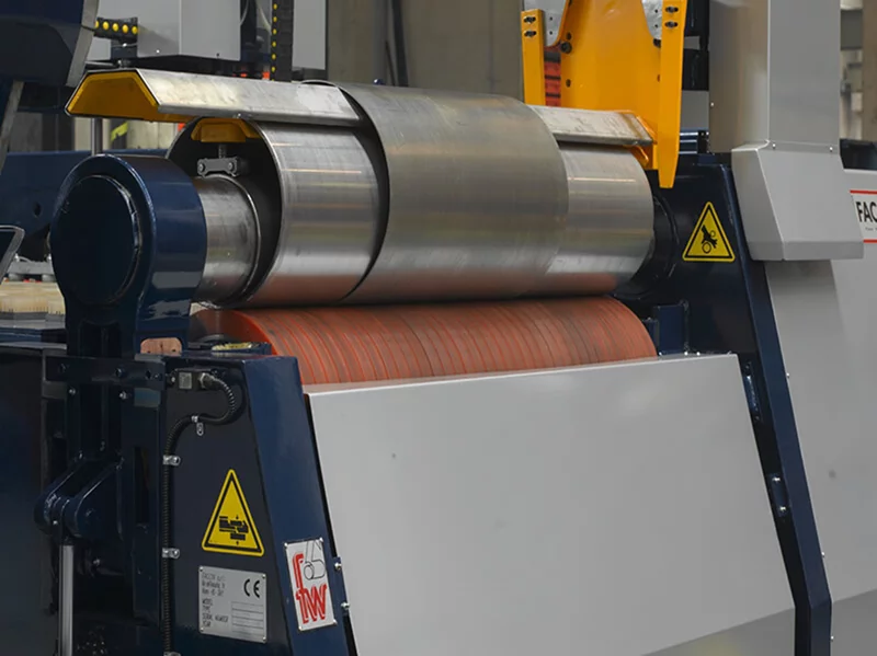
Two Roller Rolling Machine
A reference two-roll system combining a steel roll and an elastomer-covered roll, using clamping pressure and rotation to form sheet metal under PLC control.
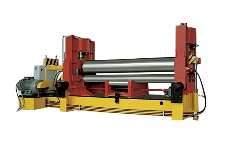
W11S-12X2000 · W11S-16X2000 +22
A three-roll system with vertical and horizontal upper-roll movement for pre-bending and rolling, with adjustable support rolls and digital position indication.
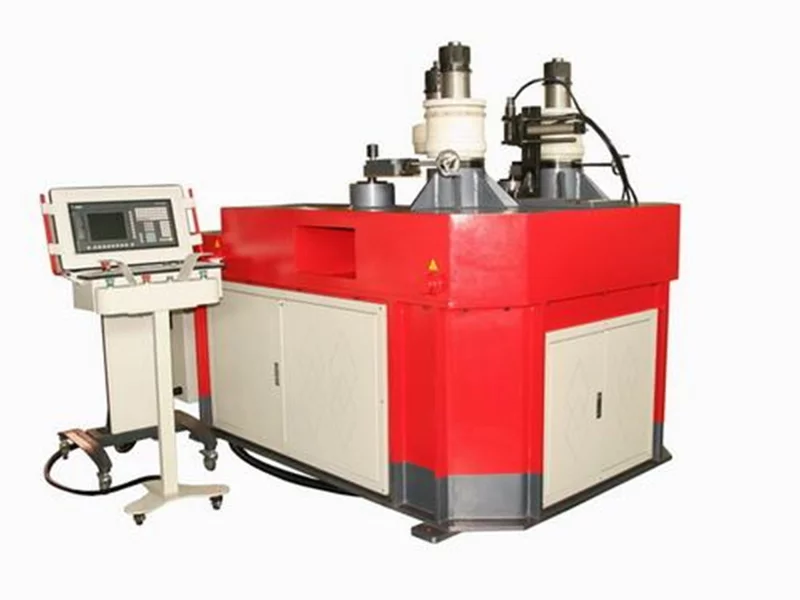
RR 100-TNC
A reference profile-bending system with three hydraulically driven rolls and servo-controlled curvature adjustment for angle, flat bar, round tube and other sections.
LET’S BUILD SOMETHING BETTER